Debert Water Utility Building – Feasibility Study
This feasibility study, submitted by the ReCover Initiative, outlines a net-zero scenario using a panelized deep retrofit solution for a small commercial building in Debert, NS.
| Building Type | Municipal Water Utility | Location | Debert, NS |
| Year Built | 1979 | Structure Type | Wood (Building A), Concrete Block (Building B) |
| Post-Retrofit Total Floor Area | 716m2 | Climate Zone | 6 |
| Heating Degree Days | 4500 |
Project Team
- Habit Studio ( Building Science Advisor )
- RDH ( Energy Modelling )
- Mechanical & Electrical Engineer ( Mechanical & Electrical Engineer )
- Seefar Building Analytics ( Financial Model )
- Stanley Francispillai ( Hygrothermal )
- QSolv ( Cost Consultant )
- Fatma Osman ( Embodied Carbon modeling )
- Natural Resources Canada, The Atmospheric Fund, Nova Scotia Department of Natural Resources and Renewables, City of Burlington, Municipality of Colchester, Halifax Regional Municipality, Town of New Glasgow, City of Oakville, City of Saskatoon ( Funders )
Project Priorities
- Reduce Energy Consumption
- Achieve Net Zero or Net Zero Ready
- Reduce GHG Emissions
- Other
Project Goals
The objectives of this study were to de-risk investment in deep retrofits in Canada, to provide evidence on the effectiveness and scalability of a panelized deep retrofit approach and to build confidence and experience in deep retrofits among Canadian municipalities and industry stakeholders.
The goals for the Deep Retrofits explored included:
- Develop a scenario that achieves an Energy Use Intensity (EUI) reduction of 50%.
- Develop a Net Zero Energy Ready (NZER) scenario.
- Develop a Net Zero Energy (NZE) scenario with the addition of onsite renewables.
- All solutions minimize occupant disruption during construction.
- All solutions target minimal embodied carbon.
- Identify the retrofit pathway to the lowest Total Cost of Building Ownership.
- Demonstrate a calculated payback of 20 years or better.
Project Description
The Retrofit Story
Existing Building Details
Overview
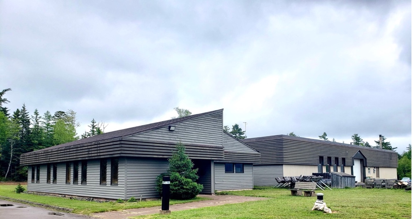
The Debert Water Utility Building is a one-storey structure with a gross floor area of 718m2 (7,728 sq. ft) consisting of two wings connected by an enclosed walkway.
Building A is a 181m2 (1,948 sq.ft.) office space which is rented out to an engineering company. Building B is a 537m2 (5,780 sq.ft.) maintenance facility used for servicing and storage of equipment and contains an office area.
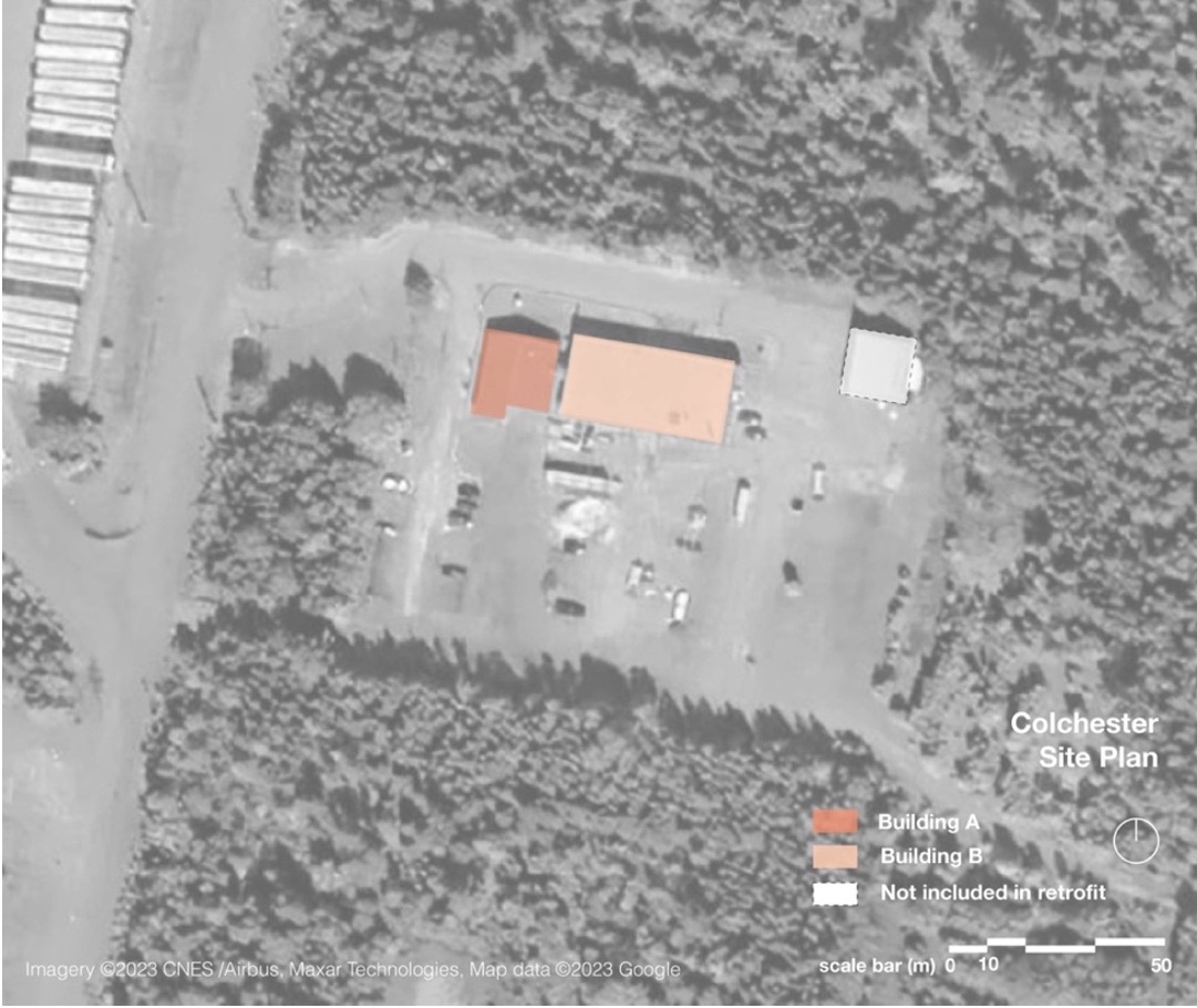
Debert is a rural, predominantly agricultural community in Colchester County, NS. The Water Utility Building is in an industrial area surrounded by woodland. It was built in 1979 as a Tree Breeding Centre for the Nova Scotia Department of Lands and Forests.
In 2021 the Municipality of Colchester implemented Carbon-Free Colchester, their Community Energy and Emissions Plan which targets net-zero Greenhouse Gas (GHG) emissions by 2050. Energy conservation through building upgrades, including retrofits, and building electrification are key pillars of the plan. Colchester has set a goal for deep retrofits to 80% of their existing buildings by 2040, and net-zero retrofits to all municipally owned buildings by 2035.
Existing Envelope
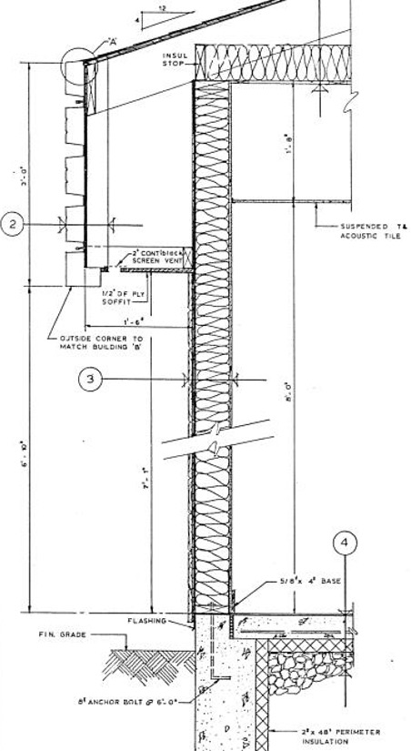
Building A is a timber structure insulated with fiberglass batt in both the exterior walls and roof. It has 2” of continuous sub-slab rigid insulation and 2” of rigid insulation installed on the interior perimeter of the frost walls to a depth of 48”. Figure 3 shows the Building A existing wall section taken from the original 1979 drawings.
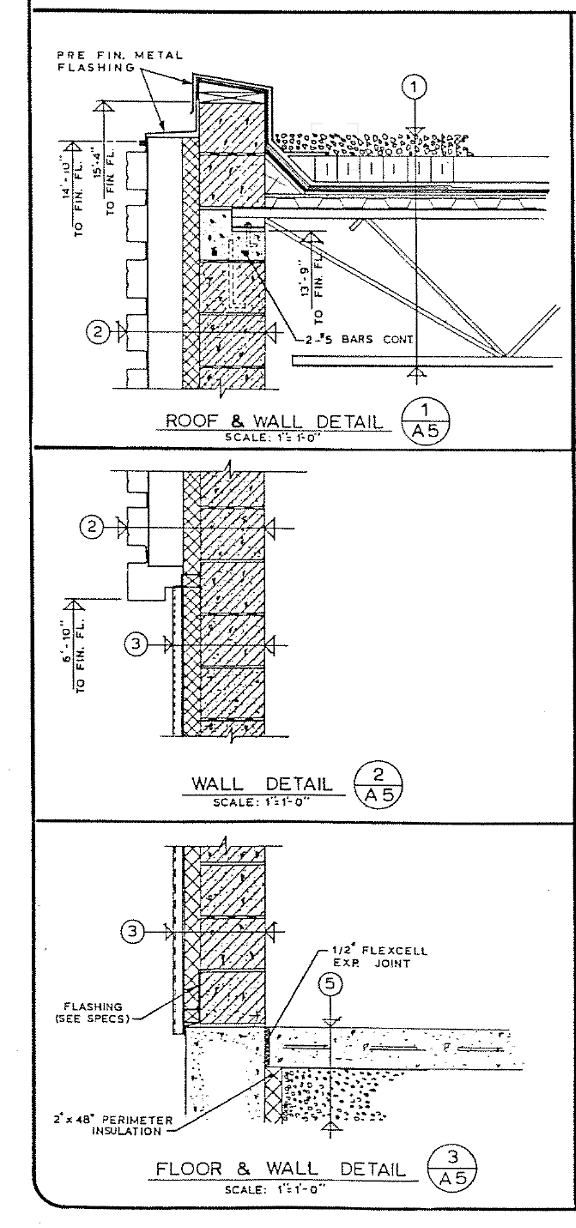
Building B has concrete block walls insulated with 2 ½” of rigid insulation on the exterior. The drawings specify a protected membrane roof assembly with 4” of rigid insulation, however the current roof is a conventional modified bitumen roof system. It is believed that the current roof has 4” of rigid insulation. The perimeter frost walls are insulated with 3” of rigid insulation. In all instances of rigid insulation in this building the material is assumed to be extruded polystyrene.
Existing Structure
Building A exterior wall section |Building B exterior wall section
Building A and B are connected via a ±7’ wide timber framed walkway. Both buildings, and the walkway, are founded on concrete slab-on-grades, with perimeter frost walls and interior strip footings to support load bearing walls.
Building A is wood framed with 2×6 studs at 16” on centre and pre-engineered timber roof trusses. The wall and roof assemblies are shown in Figure 3. The walkway between Building A and B is also wood framed with a 2” x 8” central ridge board and 2” x 6” rafters and ceiling joists at 24”. The rafters are structurally deficient based on current loading.
Building B is constructed with 10” reinforced concrete block walls and an open web steel joist (OWSJ) and corrugated metal deck roof. The existing masonry walls in Building B extend beyond the existing roof to form a parapet wall.
The walls of both buildings can support additional loading. A panelized roof solution is not structurally viable for Building A. Adding roof panels to Building B is possible, however reinforcing of the existing roof structure would be required. The recommended retrofit for both sides of the building is for new structure to bear on the existing load-bearing walls.
Existing Electrical and Mechanical
| Primary Heat Source | Oil Fired Boiler |
| Heat Distribution | Hydronic Baseboard + Unit Heaters |
| Cooling Source | 2.5 Ton Heat Pump |
| Electrical Service | 100A and 200A connection to grid |
| Electrical Distribution | 800A 3p |
| Interior Lighting | Fluorescent Fixtures |
Existing Energy Use (KWH/M2/YR)
| Lights | 28.30 |
| Plug Loads | 10.66 |
| Electric Heat | 7.06 |
| Cooling | 0.70 |
| Pump | 4.20 |
| Fans | 4.57 |
| Elec DHW | 4.68 |
| Fuel Oil | 106.39 |
Upgrade Scenario
The design team worked collaboratively to develop retrofit scenarios targeting the project objectives. The analysis assumes a ‘like for like’ retrofit where space usage, occupancy schedules, internal geometry, volume of conditioned space, and window and door dimensions and locations are consistent with existing conditions.
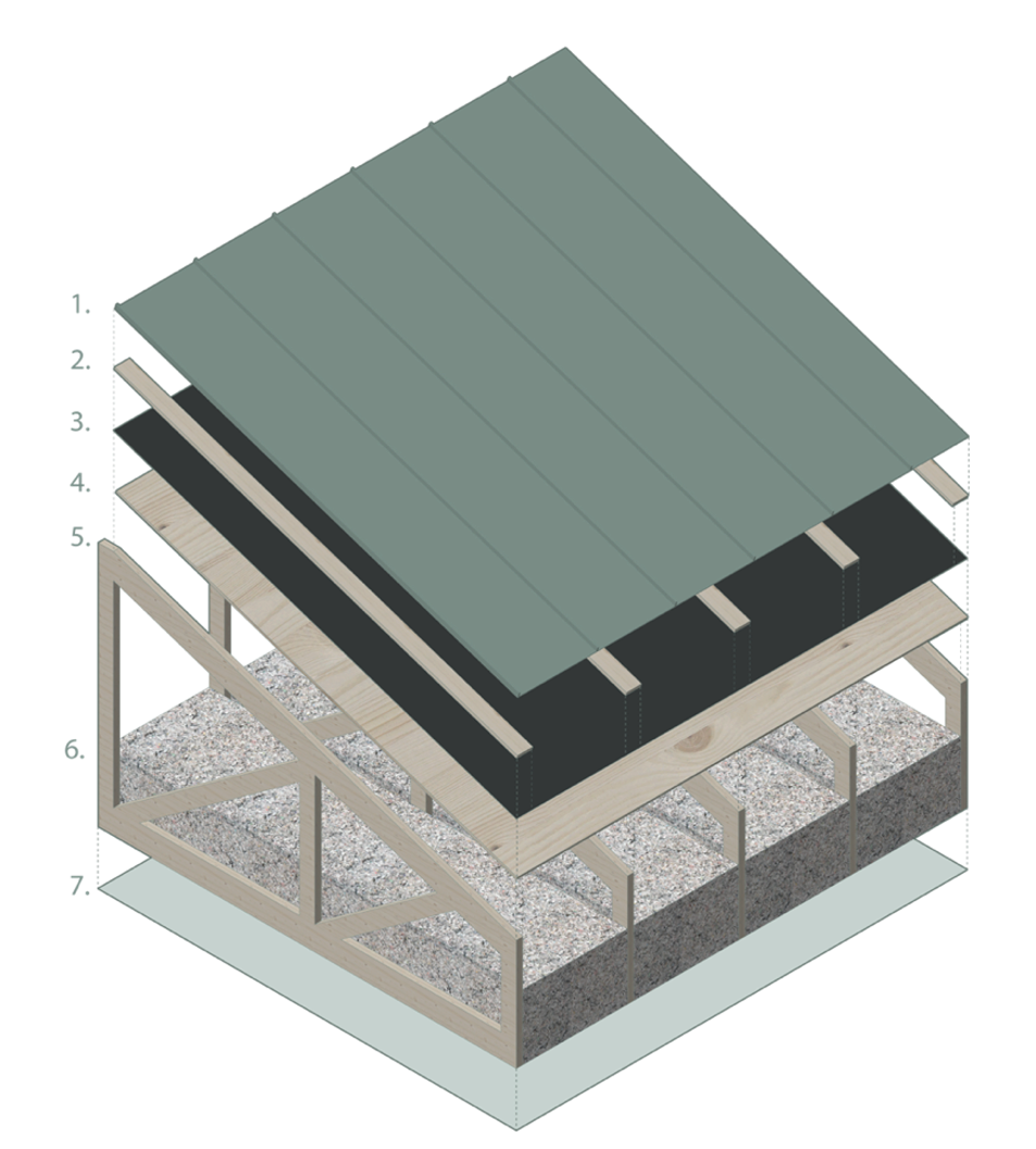
The strategy for building enclosure upgrades is to retrofit the walls with prefabricated ReCover panels and to install new pre-engineered timber roof systems over the existing roofs, supported on the existing exterior bearing walls.
A panelized roof retrofit is not recommended for Building A and although it is technically possible for Building B, it would cost more in up front and lifetime costs. A new flat roof would require costly reinforcing of the existing steel OWSJ system to support the weight of the new roof panels. It will also result in higher snow loads than the current roof, since improved thermal performance will increase snow accumulation. Flat roofs typically require more ongoing maintenance than sloped roofs, representing higher costs over the life of the building. For these reasons a truss roof is a recommended as a better investment for this retrofit.
| Existing Building | Min + Solar | |
|---|---|---|
| Effective Wall R-Value | R12 | R25 |
| Effective Roof R-Value | R15.4 | R40 |
| Windows | Vinyl, Double Glazed, R2.5 | Triple Pane R5.56 |
| Air Tightness | 2.3 L/s m² | 0.75 L/s m² |
| Heating Source | Oil Fired Boiler | Existing Oil Fired Boiler |
| Heating Distribution | Hydronic baseboards & unit heaters | Existing Hydronic baseboards & unit heaters |
| Cooling | ASHP, Packaged AC Unit | Existing ASHP, Mini-split heat pump |
| DHW | Electric Water Heater | Existing Electric Water Heater |
| Ventilation Equipment | Extract only | 90% SRE ERVs |
| Electrical Service | 800A, 3p | Existing 800A, 3p |
| Renewable | None | 42 kW Solar PV |
| 60 Year TCBO | $9,076,000 | $7,820,000 |
Panelized Solutions
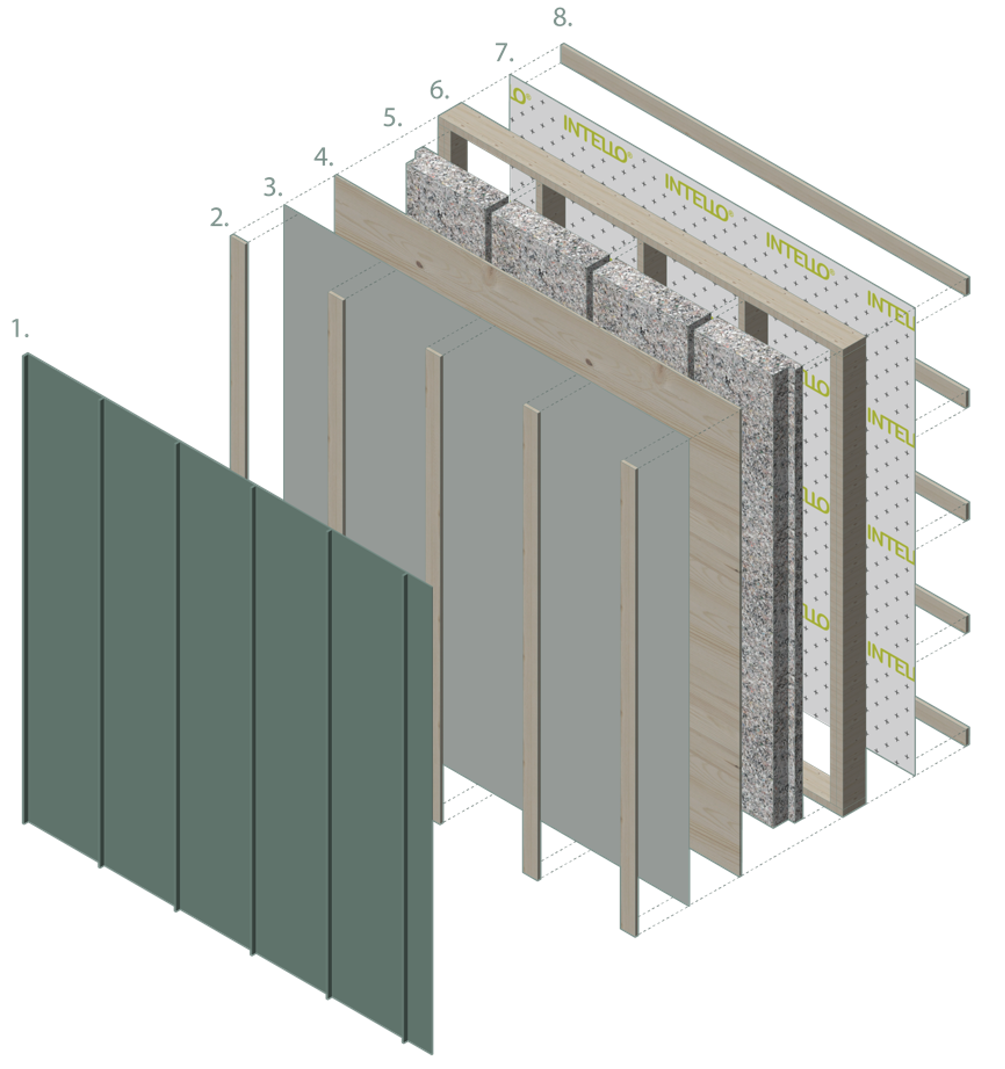
The prototype ReCover panel is a wood framed box which holds carbon storing cellulose insulation. The depth of the frame is flexible depending on the needed performance. All retrofit scenarios proposed for the Debert Water Utility Building use panels with 2×6 stud framing.
The panel components were specified to minimize moisture risks by shedding precipitation on the outside and by promoting drying activity to the exterior through the panel assembly. This is important as the existing assemblies include vapour retarding materials, including polyethylene vapour barrier and rigid foam insulation, which will inhibit drying to the interior of the building. These materials will also inhibit outward vapour drive, from the interior into the panels, however given the age and condition of the building it is highly unlikely that these materials comprise a continuous vapour barrier. The panels are be designed to promote any moisture movement that occurs from the interior to dry to the exterior.
Strapping on the interior side of the panel permits fitting adjustments against the existing walls and provides an internal air cavity that serves as a moisture buffer space for vapour diffusion from the inside to pass out through the panels. The frame backing layer is a “smart” vapour control membrane which varies in permeability depending on the relative humidity of its environment. If moisture is present between the panel and the existing walls the membrane fibers open to let moisture escape. Wood panel framing, plywood sheathing and cellulose insulation are all hygroscopic materials, meaning their fibers transport moisture from areas of higher humidity to those of lower humidity. A vapour-open water-resistive barrier (WRB) protects the outer plywood sheathing and provides a drainage plane behind the rainscreen cavity and metal siding.
PDF of Wall Panel Details | Sketchup File of Wall Panel Details
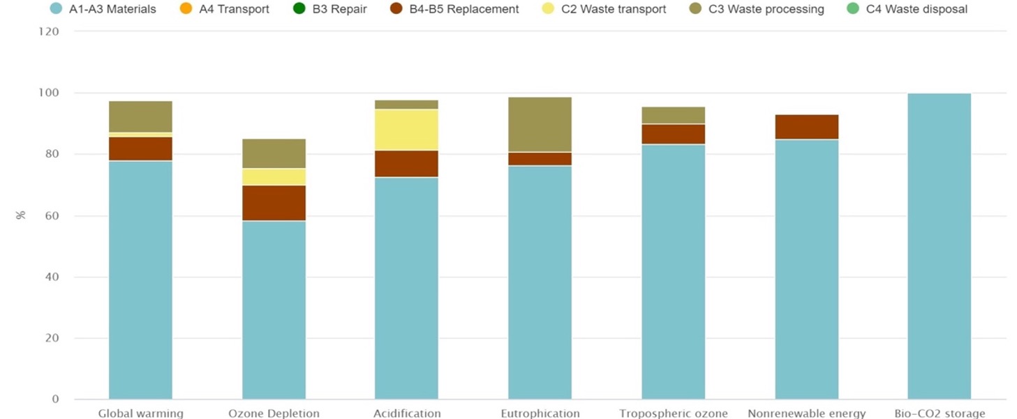
Embodied Carbon
Embodied Carbon was modeled for this project in One Click LCA. Materials modeled were based on the most representative materials available to the Canadian market with Environmental Product Declarations (EPDs) available in the One Click LCA database. The analysis was limited to embodied carbon of assembly materials being added to the existing building including panel additions to above-grade walls, roofs, below-grade components, and windows and doors. HVAC and electrical components were excluded from the analysis.
The results include a whole life cycle assessment of the building in six impact categories: Global Warming, Ozone Depletion, Acidification, Eutrophication, Formation of tropospheric ozone, Depletion of nonrenewable energy, and Biogenic carbon storage.
Total Cost of Building Ownership (TCBO)
Total Cost of Building Ownership (TCBO) analysis was conducted using the Sustainable Energy Efficient Facility Asset Renewal (SEEFAR)-Valuation© program. Calculations include costs for utilities, carbon tax, maintenance, maintenance capital (replacing major components as they age out), insurance, interest, and escalation of these costs over time. TCBO analysis typically includes property taxes, however the building is not subject to property tax.
Total Cost of Building Ownership Summary
| Base Case | Min + Solar | |
|---|---|---|
| GHG Emissions (kg) (60 Years) | 3,437,029 | 734,029 |
| EUI (kWh/m²/year) | 220.6 | 69.3 |
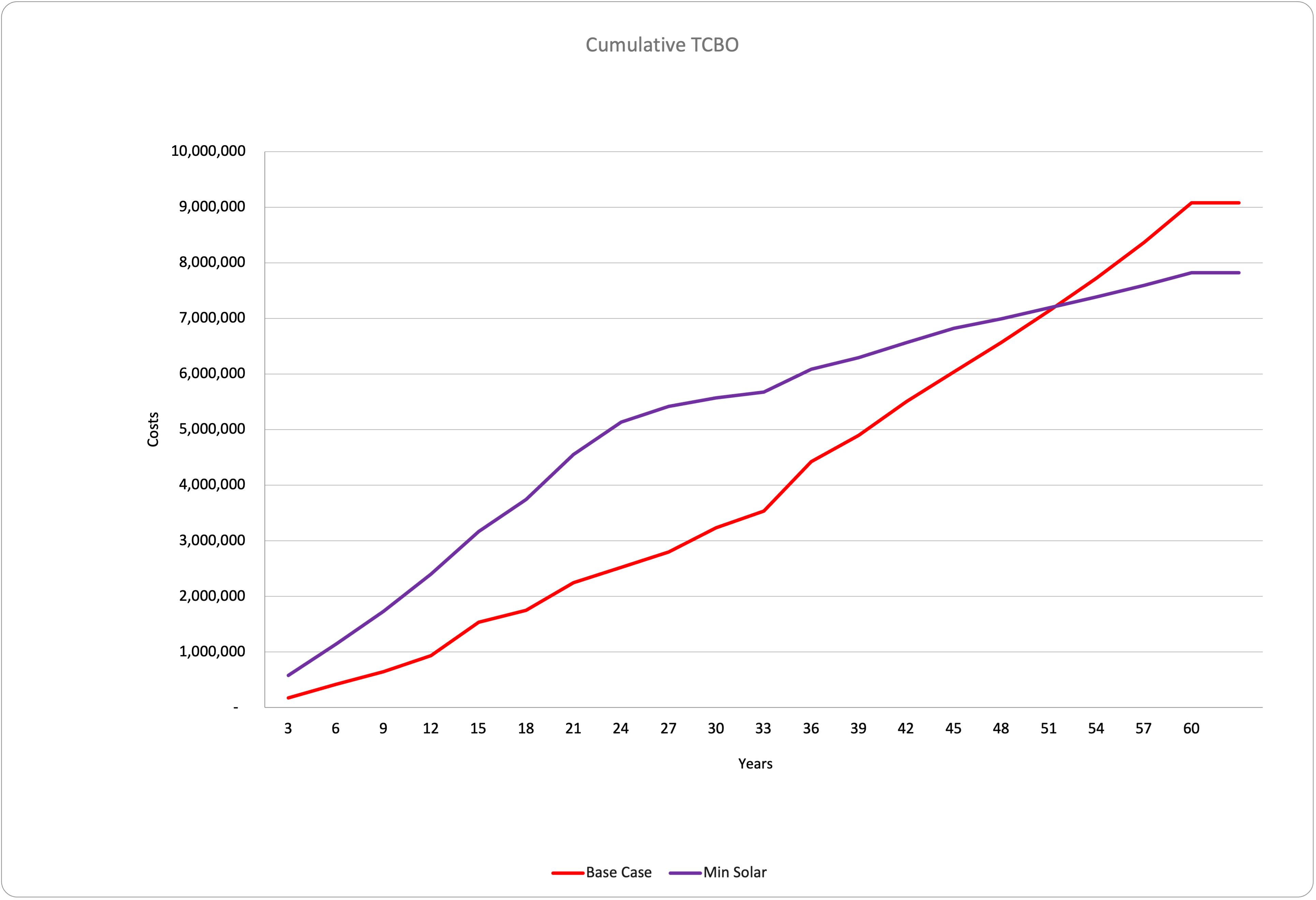
| TCBO at 60 Years | $9,076,000 | $7,820,000 |
| TCBO Savings at 60 Years | $0 | $1,256,000 |
| % Diff. from Base Case | – | 14% |
Cumulative TCBO The lowest TCBO is the Minimum Upgrade plus PV which delivers a 68% reduction in EUI for a 14% TCBO savings of $1.25M.
After 51 years the savings in operating costs from doing the retrofit will exceed the business as usual scenario.
Before & After
General |
Technical Documents
Drawings or Details
Photos